This sample project showcases Eta One’s full-scope engineering capabilities through the design of a 60 MW power plant. From concept to construction-ready deliverables, our team led every phase — including process definition, thermodynamic modeling, 3D layout, piping stress analysis, documentation, and procurement support. Whether taking full responsibility or stepping in as technical consultants, Eta One ensures precision, practicality, and seamless integration at every step of the project.
I. Project Guide Analysis
Based on the project guide and planning data provided for the selected engine, the Eta One team conducts a thorough review to determine the technical and operational requirements of the engine. This forms the foundation for designing the balance of plant (BoP) systems. The analysis ensures full alignment between the engine’s specifications and the auxiliary systems to be engineered, such as piping, cooling, ventilation, and fuel handling.
This step is critical in defining:
- The scope of required utilities
- Load profiles and operating conditions
- System constraints and interface points
- Design standards and client expectations
By starting with a deep understanding of the engine’s integration needs, we ensure that every downstream design decision is technically sound and project-aligned.
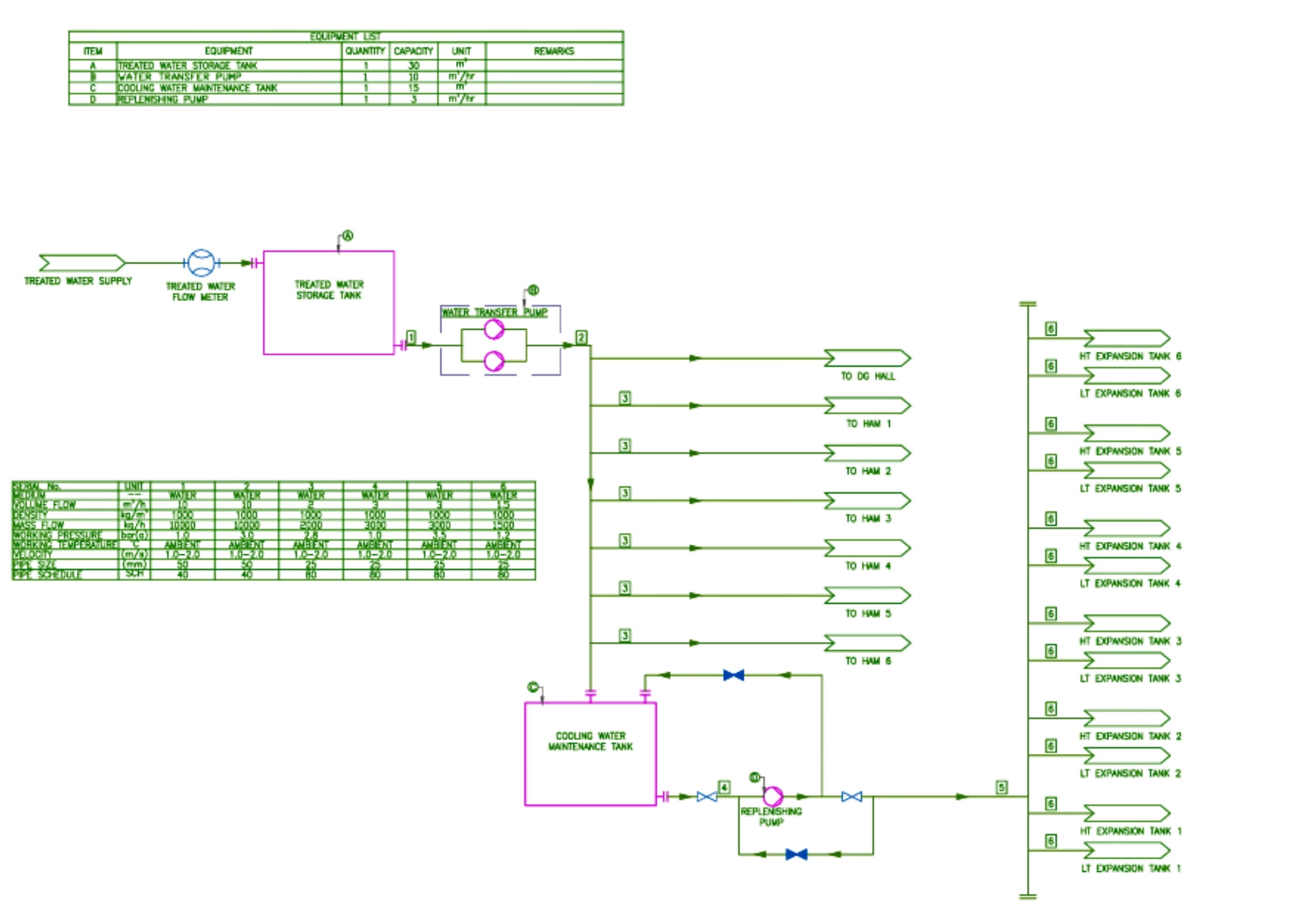
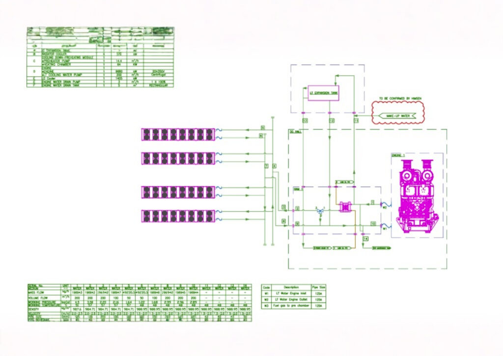
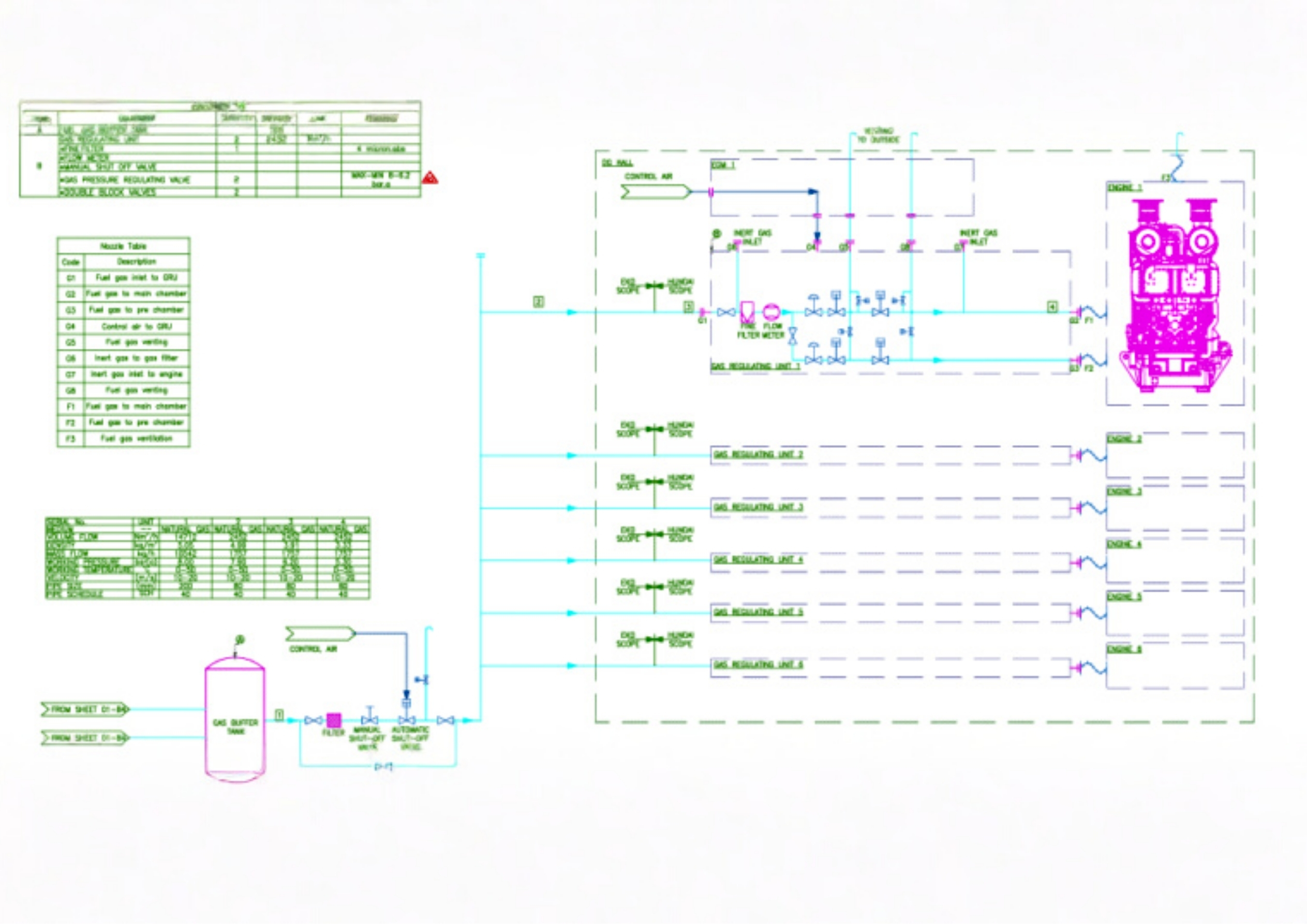
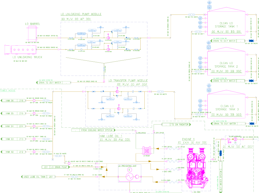
II. Process Flow Diagram Generation
After thoroughly analyzing the engine requirements and project constraints, we begin generating detailed Process Flow Diagrams (PFDs) for all auxiliary systems. These diagrams define the system architecture, flow paths, and operational logic — forming the foundation for downstream design. In parallel, we calculate the thermodynamic state at each key point in the process, including temperature, pressure, flow rate, density, and velocity. This allows us to size pumps and pipes accurately and simulate flow behavior under realistic operating conditions.
As part of this phase, we also prepare RFQs (Requests for Quotation) for all major equipment based on the defined process requirements, ensuring smooth coordination with vendors and procurement teams.
Generated PFDs include:
- Liquid Fuel Oil System
- Gas Fuel Oil System
- Lube Oil System
- Cooling Water System
- Compressed Air System
- Steam System
- Water Distribution System
- Combustion Air and Exhaust Gas System
- Oily Water System
These flow diagrams and accompanying calculations are essential for ensuring technical accuracy, supporting equipment selection, and maintaining clear coordination across systems.
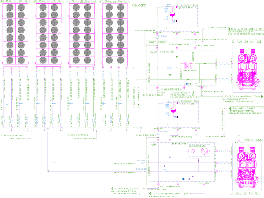
III. Piping & Instrumentation Diagram (P&ID) Development
Once the Process Flow Diagrams (PFDs) are finalized, we move forward with generating detailed Piping & Instrumentation Diagrams (P&IDs) for each system. These diagrams build upon the PFDs by incorporating exact pipe routing, equipment tags, valve types, and all necessary instrumentation.
Each P&ID includes:
- Pipe identifiers and specifications (diameter, material, insulation)
- Valve types and codes (manual, control, safety, check valves, etc.)
- Equipment tags and reference numbers aligned with the asset list
- Instrumentation (pressure, flow, temperature sensors and transmitters)
- Control loops and interlocks
- Line numbers and direction of flow
The P&IDs serve as a blueprint for construction, control system integration, and commissioning. They ensure that all stakeholders — from engineers to contractors — are aligned on system functionality, safety requirements, and operational logic.

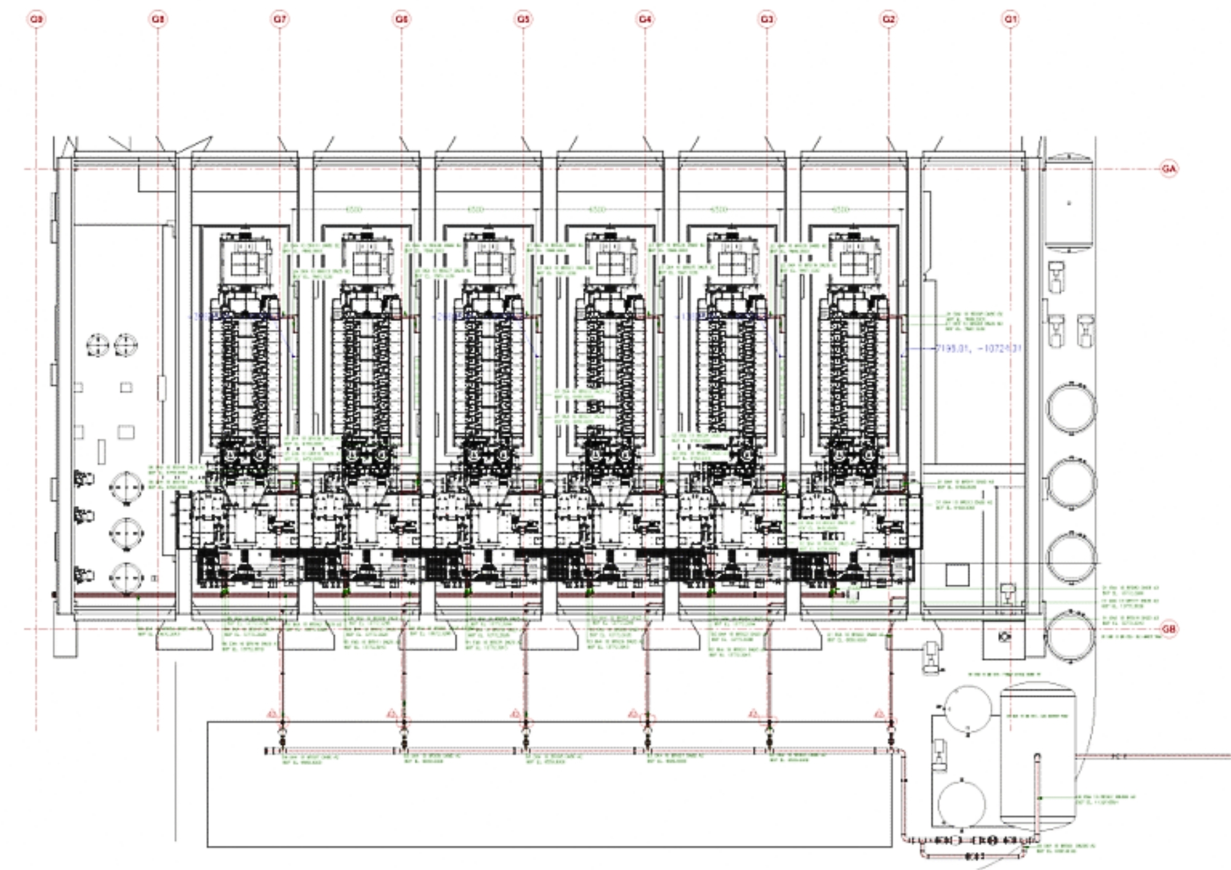
IV. General Arrangement & Equipment Foundation Layout
Once the process and instrumentation design is established, we develop the General Arrangement (GA) of the power plant, placing all major equipment in a 3D layout that reflects real-world constraints, operational logic, and maintainability.
This includes the detailed positioning of:
- Engines, pumps, tanks, and heat exchangers
- Electrical and control rooms
- Pipe racks and utility corridors
- Access platforms and walkways
Simultaneously, we generate the Equipment Foundation Layout, ensuring that each component is structurally supported and properly aligned with civil and structural design requirements.
All layouts are developed in 3D, allowing the client to visualize the entire plant before construction begins. This enables:
- Early clash detection between systems
- Verification of space requirements and access
- Coordination with civil, architectural, and electrical teams
- Smoother installation and reduced rework on site
A well-thought-out general arrangement is the backbone of a successful power plant — combining engineering logic with physical reality.
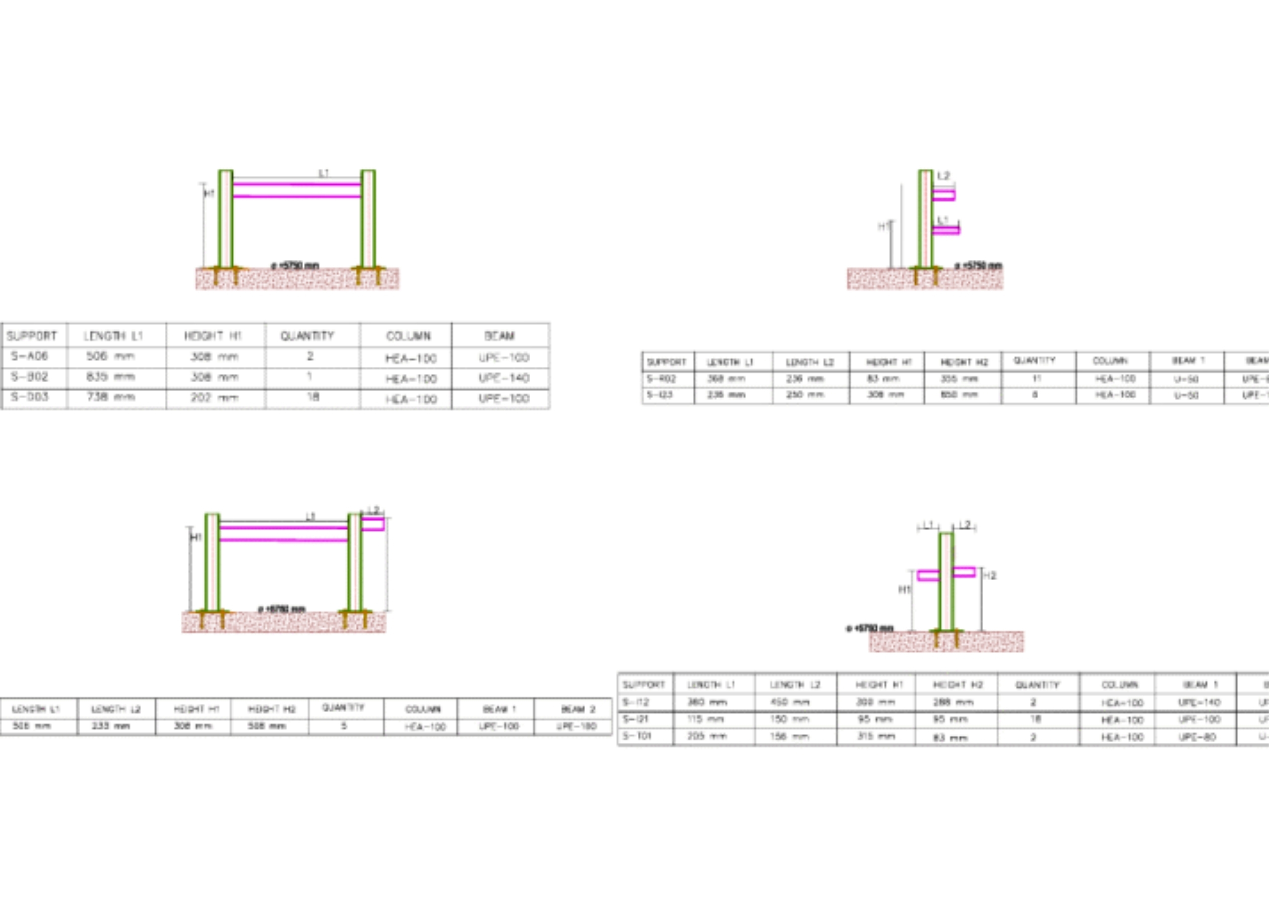
V. Piping & Supports Layout
Following the General Arrangement, we develop the full 3D piping layout of the plant, detailing every line route based on functionality, accessibility, and space constraints. This includes main process lines, auxiliary services, drains, and vents, all coordinated within the overall plant model.
The layout phase focuses on:
- Optimized pipe routing for flow efficiency and maintenance access
- Segregation of hot and cold lines
- Avoiding clashes with structural, electrical, and mechanical components
- Clear definition of supports, guides, anchors, and expansion loops
To ensure safety and long-term reliability, we perform a detailed piping stress analysis using tools like CAESAR II. This evaluates the impact of:
- Thermal expansion and contraction
- Weight-induced stresses on supports
- Wind or seismic loads (if applicable)
- Equipment nozzle loads and flexibility requirements
The result is a fully integrated piping model that is both mechanically sound and installation-ready, ensuring the system operates safely under all expected conditions.
Smart piping layout and stress analysis prevent future failures and reduce costly surprises during operation.
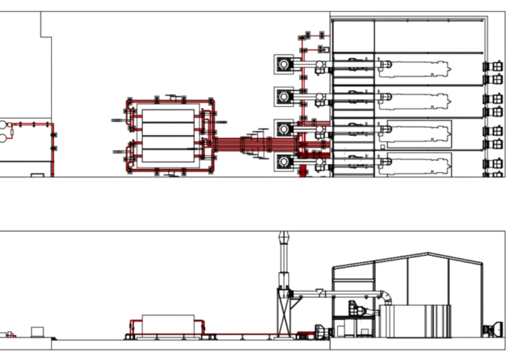
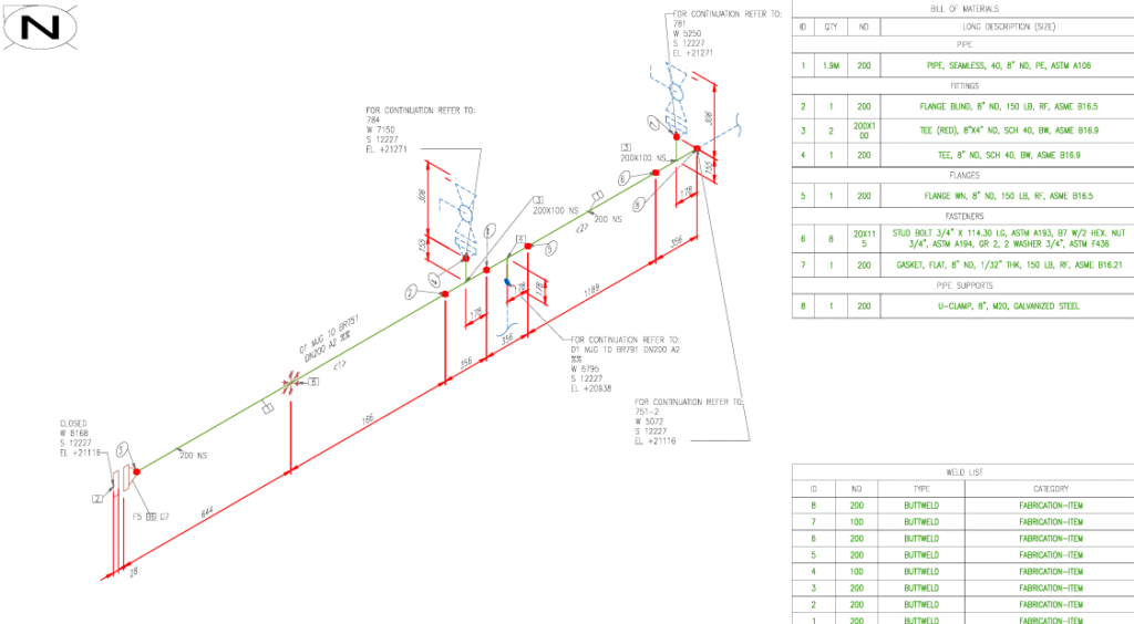
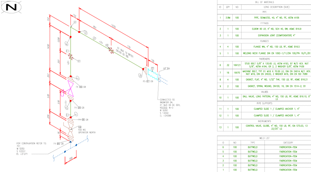
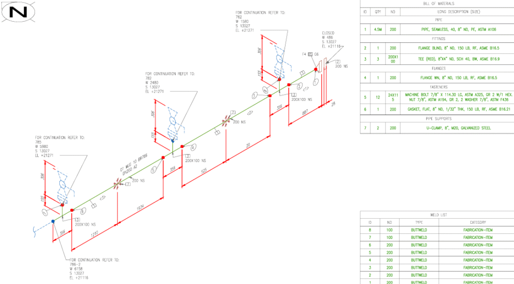
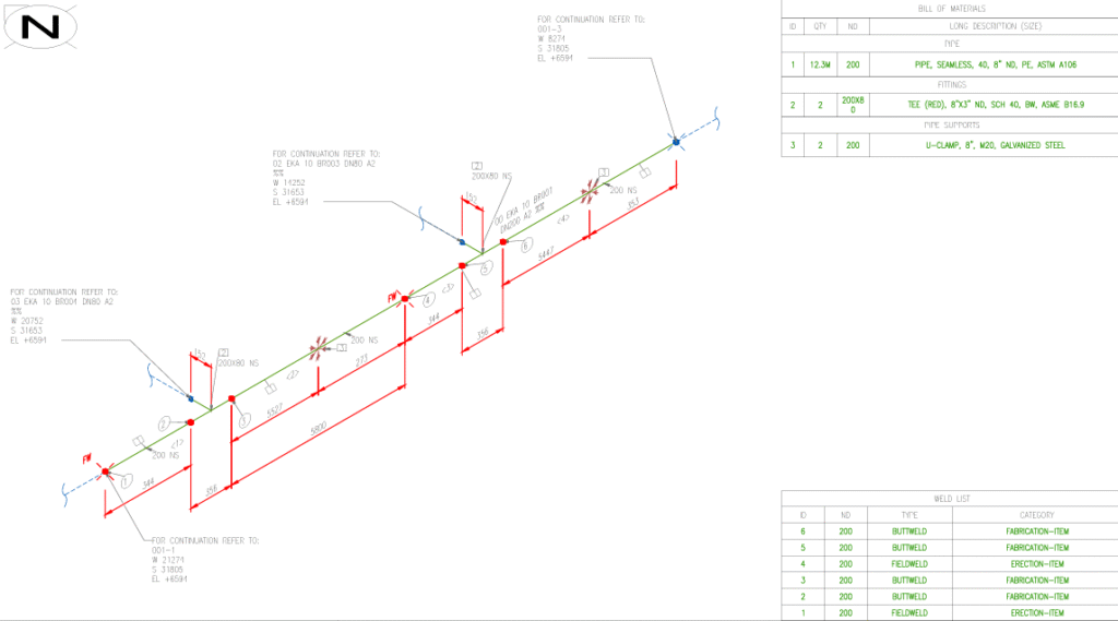
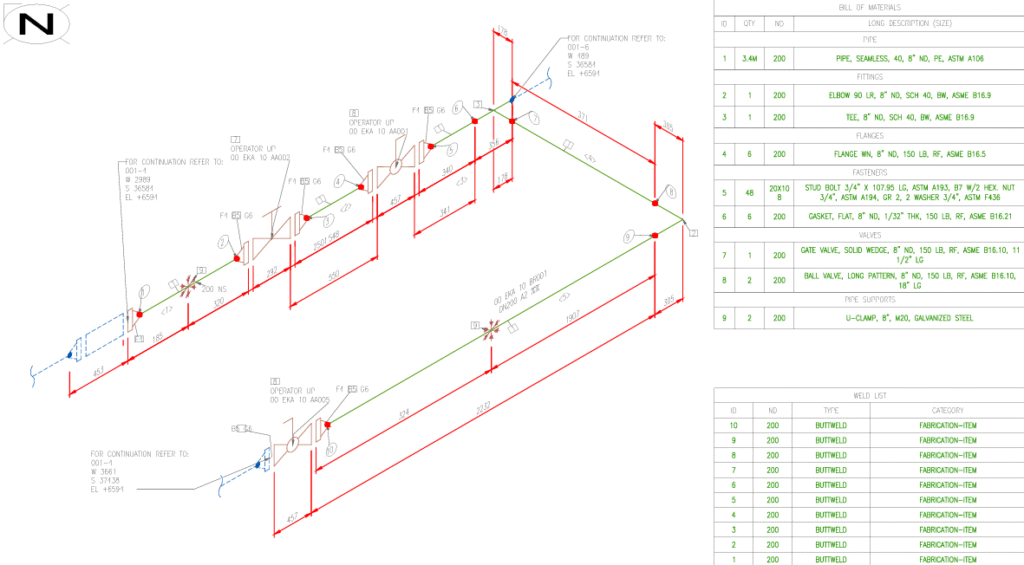
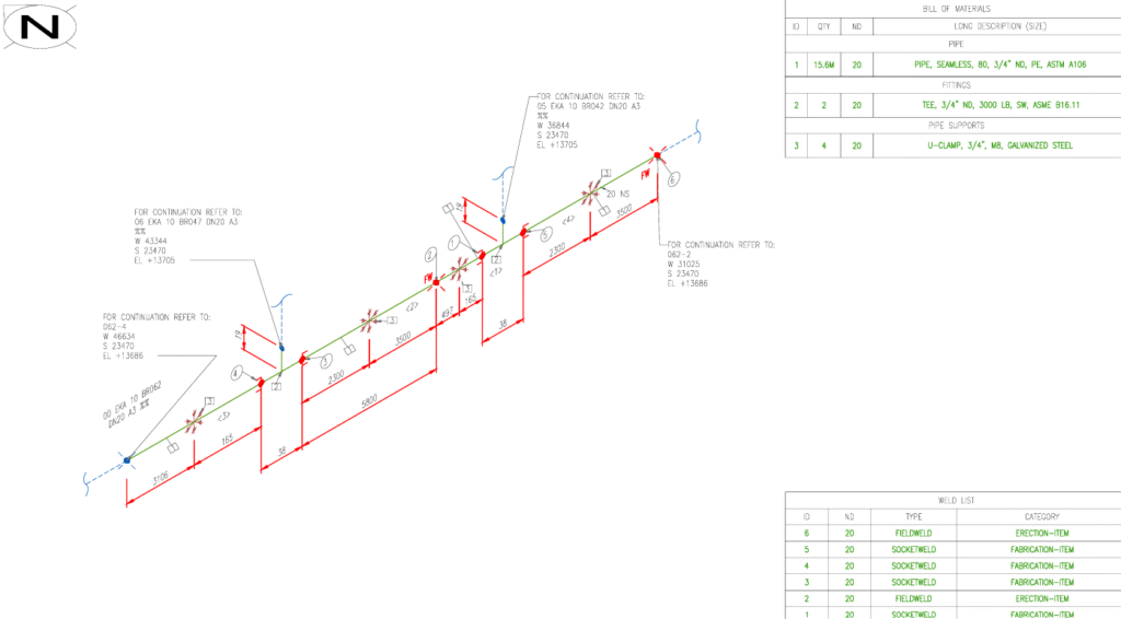
VI. Ortho Views & Isometric Generation
After completing the 3D piping layout and validation, we generate orthographic views and isometric drawings to support fabrication, installation, and quality control on-site. These deliverables are directly derived from the 3D model to ensure full consistency with the design.
Each drawing includes:
- Pipe and equipment tags aligned with the approved P&IDs
- Spool-by-spool breakdown for fabrication and assembly
- Detailed representation of welds, fittings, flanges, reducers, and valves
- Dimensions, elevations, and support locations
- Clear identification of flow direction, pipe specs, and line numbers
These drawings serve as essential documents for:
- Prefabrication workshops
- On-site assembly and inspection
- Verification of compliance with design standards
- Procurement coordination (BOM consistency)
Isometric and orthographic drawings transform your 3D model into buildable reality — with clarity, precision, and traceability down to every weld.
VII. Bill of Quantities (BOQ)
As a final step in the design phase, we prepare a comprehensive Bill of Quantities (BOQ) for all systems covered in the project. The BOQ translates the full 3D model and associated drawings into an itemized, quantifiable list — providing a foundation for accurate budgeting, procurement, and execution.
Our BOQ includes:
- Tagged piping materials (line by line)
- Valves, fittings, and special parts
- Supports, anchors, and spring hangers
- Equipment list with specifications and tag numbers
- Insulation quantities based on system classification
- Estimated weights and volumes for transport and logistics
- Breakdown per system, area, or phase, as required
All quantities are derived directly from the validated 3D model and cross-referenced with the P&IDs to ensure alignment and eliminate discrepancies.
A well-prepared BOQ is more than just a list — it’s a strategic tool for planning, budgeting, and executing your project with confidence.